Download Data Center, Specialist.JN0-480.VCEplus.2024-03-14.23q.vcex
| Vendor: | Juniper |
| Exam Code: | JN0-480 |
| Exam Name: | Data Center, Specialist |
| Date: | Mar 14, 2024 |
| File Size: | 962 KB |
How to open VCEX files?
Files with VCEX extension can be opened by ProfExam Simulator.
Discount: 20%
Demo Questions
Question 1
What does EVPN use lo identity which remote leaf device advertised the EVPN route?
- a route distinguisher value
- a community tag
- a route target value
- a VRF target value
Correct answer: A
Explanation:
EVPN uses a route distinguisher (RD) value to identify which remote leaf device advertised the EVPN route. An RD is a 64-bit value that is prepended to the EVPN NLRI to create a unique VPNv4 or VPNv6 prefix. The RD value is usually derived from the IP address of the PE that originates the EVPN route. By comparing the RD values of different EVPN routes, a PE can determine which remote PE advertised the route and which VRF the route belongs to. The other options are incorrect because:B) a community tag is wrong because a community tag is an optional transitive BGP attribute that can be used to group destinations that share some common properties. A community tag does not identify the source of the EVPN route.C) a route target value is wrong because a route target (RT) value is an extended BGP community that is used to control the import and export of EVPN routes between VRFs. An RT value does not identify the source of the EVPN route.D) a VRF target value is wrong because there is no such thing as a VRF target value in EVPN. A VRF is a virtual routing and forwarding instance that isolates the IP traffic of different VPNs on a PE. A VRF does not have a target value associated with it.Reference:EVPN FundamentalsRFC 9136 - IP Prefix Advertisement in Ethernet VPN (EVPN)EVPN Type-5 Routes: IP Prefix AdvertisementUnderstanding EVPN Pure Type 5 Routes EVPN uses a route distinguisher (RD) value to identify which remote leaf device advertised the EVPN route. An RD is a 64-bit value that is prepended to the EVPN NLRI to create a unique VPNv4 or VPNv6 prefix. The RD value is usually derived from the IP address of the PE that originates the EVPN route. By comparing the RD values of different EVPN routes, a PE can determine which remote PE advertised the route and which VRF the route belongs to. The other options are incorrect because:
B) a community tag is wrong because a community tag is an optional transitive BGP attribute that can be used to group destinations that share some common properties. A community tag does not identify the source of the EVPN route.
C) a route target value is wrong because a route target (RT) value is an extended BGP community that is used to control the import and export of EVPN routes between VRFs. An RT value does not identify the source of the EVPN route.
D) a VRF target value is wrong because there is no such thing as a VRF target value in EVPN. A VRF is a virtual routing and forwarding instance that isolates the IP traffic of different VPNs on a PE. A VRF does not have a target value associated with it.Reference:
EVPN Fundamentals
RFC 9136 - IP Prefix Advertisement in Ethernet VPN (EVPN)
EVPN Type-5 Routes: IP Prefix Advertisement
Understanding EVPN Pure Type 5 Routes
Question 2
Exhibit.

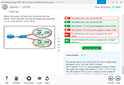
You connect two single-homed servers using Juniper Apstra as shown in the exhibit. You are using the ERB design blueprint with two virtual networks in a common routing zone.
In this scenario, which two types of VXLAN tunnels will be automatically created by the EVPN control plane? (Choose two.)
- EVPN signaled route Type-8 VXLAN tunnels
- EVPN signaled route Type-3 VXLAN tunnels
- EVPN signaled route Type-6 VXLAN tunnels
- EVPN signaled route Type-2 VXLAN tunnels
Correct answer: BD
Explanation:
According to the Juniper documentation1, EVPN route Type-3 is used to advertise the IP address of the VTEP and the VNIs that it supports. This allows the VTEPs to discover each other and form VXLAN tunnels for the VNIs that they have in common. EVPN route Type-2 is used to advertise the MAC and IP addresses of the hosts connected to the VTEPs. This allows the VTEPs to learn the MAC-to-IP bindings and the MAC-to-VTEP mappings for the hosts in the same VNI. Therefore, these two types of VXLAN tunnels will be automatically created by the EVPN control plane when using Juniper Apstra with the ERB design blueprint and two virtual networks in a common routing zone.Reference:Example: Configure an EVPN-VXLAN Centrally-Routed Bridging Fabric According to the Juniper documentation1, EVPN route Type-3 is used to advertise the IP address of the VTEP and the VNIs that it supports. This allows the VTEPs to discover each other and form VXLAN tunnels for the VNIs that they have in common. EVPN route Type-2 is used to advertise the MAC and IP addresses of the hosts connected to the VTEPs. This allows the VTEPs to learn the MAC-to-IP bindings and the MAC-to-VTEP mappings for the hosts in the same VNI. Therefore, these two types of VXLAN tunnels will be automatically created by the EVPN control plane when using Juniper Apstra with the ERB design blueprint and two virtual networks in a common routing zone.Reference:Example: Configure an EVPN-VXLAN Centrally-Routed Bridging Fabric
Question 3
In the Juniper Apstra design phase, which object dictates port count, port speed, and how the ports would be used?
- logical devices
- rack type
- network devices
- interface map
Correct answer: D
Explanation:
Interface maps are objects that map interfaces between logical devices and physical hardware devices in the Juniper Apstra design phase. They dictate port count, port speed, and how the ports would be used for achieving the intended network configuration rendering. Interface maps also allow you to select device ports, transformations, and interfaces, provision breakout ports, and disable unused ports. For more information, seeInterface Maps (Datacenter Design).Reference:Interface Maps (Datacenter Design)DesignInterface Maps Introduction Interface maps are objects that map interfaces between logical devices and physical hardware devices in the Juniper Apstra design phase. They dictate port count, port speed, and how the ports would be used for achieving the intended network configuration rendering. Interface maps also allow you to select device ports, transformations, and interfaces, provision breakout ports, and disable unused ports. For more information, seeInterface Maps (Datacenter Design).Reference:
Interface Maps (Datacenter Design)
Design
Interface Maps Introduction
Question 4
You want to keep virtual networks isolated from each other within the Juniper Apstra system.
In this scenario, what are three ways to accomplish this task? (Choose three.)
- Disable IPv4 connectivity when creating the virtual network within the same Routing Zone.
- Enable Security Policy for virtual networks in the same Routing Zone.
- Disable Route Target exports when creating the Routing Zones.
- Use Connectivity Templates to block access within the same Routing Zone.
- Put each network in different Routing Zones.
Correct answer: BDE
Explanation:
To keep virtual networks isolated from each other within the Juniper Apstra system, you can use one or more of the following methods:Enable Security Policy for virtual networks in the same Routing Zone.This allows you to define rules that control the traffic flow between different virtual networks within the same routing zone. You can specify the source and destination virtual networks, the protocol, the port, and the action (allow or deny) for each rule.The security policy is applied on the ingress interface of the leaf devices1.Use Connectivity Templates to block access within the same Routing Zone.This allows you to customize the connectivity between different racks within the same routing zone. You can create templates that define the link type, the routing protocol, and the access control list (ACL) for each rack pair.The ACL can be used to filter the traffic based on the source and destination IP addresses, the protocol, and the port2.Put each network in different Routing Zones.This allows you to create logical boundaries between different virtual networks based on the route target (RT) values. A routing zone is a collection of virtual networks that share the same RT for importing and exporting routes.Virtual networks in different routing zones do not exchange routes with each other, unless you configure remote EVPN gateways to connect them3.Reference:Security PolicyConnectivity TemplatesRouting Zones To keep virtual networks isolated from each other within the Juniper Apstra system, you can use one or more of the following methods:
Enable Security Policy for virtual networks in the same Routing Zone.This allows you to define rules that control the traffic flow between different virtual networks within the same routing zone. You can specify the source and destination virtual networks, the protocol, the port, and the action (allow or deny) for each rule.The security policy is applied on the ingress interface of the leaf devices1.
Use Connectivity Templates to block access within the same Routing Zone.This allows you to customize the connectivity between different racks within the same routing zone. You can create templates that define the link type, the routing protocol, and the access control list (ACL) for each rack pair.The ACL can be used to filter the traffic based on the source and destination IP addresses, the protocol, and the port2.
Put each network in different Routing Zones.This allows you to create logical boundaries between different virtual networks based on the route target (RT) values. A routing zone is a collection of virtual networks that share the same RT for importing and exporting routes.Virtual networks in different routing zones do not exchange routes with each other, unless you configure remote EVPN gateways to connect them3.
Reference:
Security Policy
Connectivity Templates
Routing Zones
Question 5
Exhibit.

The 10.100.0.0/16 route is being advertised into your BGP IP fabric. ECMP load balancing has been properly enabled on all devices
In this scenario, how many routes will the leaf device in AS 65000 receive for the 10.100.0.0/16 prefix?
- 3
- 1
- 2
- 4
Correct answer: A
Explanation:
The leaf device in AS 65000 will receive three routes for the 10.100.0.0/16 prefix, one from each spine device in AS 65001, AS 65002, and AS 65003. Since ECMP load balancing is enabled, the leaf device will install all three routes in its routing table and distribute the traffic among them. The other options are incorrect because:B) 1 is wrong because the leaf device will not receive only one route for the prefix. It will receive multiple routes from different spine devices and use ECMP to load balance among them.C) 2 is wrong because the leaf device will not receive only two routes for the prefix. It will receive three routes from three spine devices, as explained above.D) 4 is wrong because the leaf device will not receive four routes for the prefix. It will receive three routes from three spine devices, as explained above. The fourth spine device in AS 65004 is not directly connected to the leaf device and will not advertise the prefix to it.Reference:IP Fabric Underlay Network Design and ImplementationBGP Multipath load sharing iBGP and eBGPECMP Load Balancing The leaf device in AS 65000 will receive three routes for the 10.100.0.0/16 prefix, one from each spine device in AS 65001, AS 65002, and AS 65003. Since ECMP load balancing is enabled, the leaf device will install all three routes in its routing table and distribute the traffic among them. The other options are incorrect because:
B) 1 is wrong because the leaf device will not receive only one route for the prefix. It will receive multiple routes from different spine devices and use ECMP to load balance among them.
C) 2 is wrong because the leaf device will not receive only two routes for the prefix. It will receive three routes from three spine devices, as explained above.
D) 4 is wrong because the leaf device will not receive four routes for the prefix. It will receive three routes from three spine devices, as explained above. The fourth spine device in AS 65004 is not directly connected to the leaf device and will not advertise the prefix to it.Reference:
IP Fabric Underlay Network Design and Implementation
BGP Multipath load sharing iBGP and eBGP
ECMP Load Balancing
Question 6
Using the Juniper Apstra multitenancy capabilities, which approach will allow a tenant to interconnect two different routing zones?
- Interconnection is the default behavior.
- Use interconnection through the fabric spine nodes.
- Interconnection cannot be enabled.
- Use interconnection through an external gateway.
Correct answer: D
Explanation:
According to the Juniper documentation1, a routing zone is an L3 domain, the unit of tenancy in multi-tenant networks. You create routing zones for tenants to isolate their IP traffic from one another, thus enabling tenants to re-use IP subnets. In addition to being in its own VRF, each routing zone can be assigned its own DHCP relay server and external system connections. You can create one or more virtual networks within a routing zone, which means a tenant can stretch its L2 applications across multiple racks within its routing zone. For virtual networks with Layer 3 SVI, the SVI is associated with a Virtual Routing and Forwarding (VRF) instance for each routing zone isolating the virtual network SVI from other virtual network SVIs in other routing zones. If you're using multiple routing zones, external system connections must be from leaf switches in the fabric. Routing between routing zones must be accomplished with external systems. Therefore, the correct answer is D. Use interconnection through an external gateway.Reference:Routing Zones According to the Juniper documentation1, a routing zone is an L3 domain, the unit of tenancy in multi-tenant networks. You create routing zones for tenants to isolate their IP traffic from one another, thus enabling tenants to re-use IP subnets. In addition to being in its own VRF, each routing zone can be assigned its own DHCP relay server and external system connections. You can create one or more virtual networks within a routing zone, which means a tenant can stretch its L2 applications across multiple racks within its routing zone. For virtual networks with Layer 3 SVI, the SVI is associated with a Virtual Routing and Forwarding (VRF) instance for each routing zone isolating the virtual network SVI from other virtual network SVIs in other routing zones. If you're using multiple routing zones, external system connections must be from leaf switches in the fabric. Routing between routing zones must be accomplished with external systems. Therefore, the correct answer is D. Use interconnection through an external gateway.Reference:Routing Zones
Question 7
Exhibit.

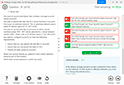
In the EVPN-VXLAN data center fabric bridged overlay architecture shown in the exhibit, the servers are connected to Lead and Leat6 using the same virtual network identifier (VNI).
Which two statements are correct in this scenario? (Choose two.)
- The underlay must use IRB interfaces.
- The underlay must be provisioned with PIMv2.
- Loopback IPv4 addresses must be advertised into the EBGP underlay from leaf and spine devices.
- The underlay EBGP peering's must be established between leaf and spine devices.
Correct answer: CD
Explanation:
In the EVPN-VXLAN data center fabric bridged overlay architecture shown in the exhibit, the servers are connected to Leaf1 and Leaf6 using the same virtual network identifier (VNI). This means that the servers belong to the same Layer 2 domain and can communicate with each other using VXLAN tunnels across the fabric. The underlay network provides the IP connectivity between the leaf and spine devices, and it uses EBGP as the routing protocol. Therefore, the following two statements are correct in this scenario:Loopback IPv4 addresses must be advertised into the EBGP underlay from leaf and spine devices. This is because the loopback addresses are used as the source and destination IP addresses for the VXLAN tunnels, and they must be reachable by all the devices in the fabric. The loopback addresses are also used as the router IDs and the BGP peer addresses for the EBGP sessions.The underlay EBGP peering's must be established between leaf and spine devices. This is because the EBGP sessions are used to exchange the underlay routing information and the EVPN routes for the overlay network. The EBGP sessions are established using the loopback addresses of the devices, and they follow a spine-and-leaf topology, where each leaf device peers with all the spine devices, and each spine device peers with all the leaf devices.The following two statements are incorrect in this scenario:The underlay must use IRB interfaces. This is not true, because the underlay network does not provide any Layer 3 gateway functionality for the overlay network. The IRB interfaces are used to provide inter-VXLAN routing within the fabric, which is not the case in the bridged overlay architecture. The IRB interfaces are used in the edge-routed bridging (ERB) or the centrally-routed bridging (CRB) architectures, which are different from the bridged overlay architecture.The underlay must be provisioned with PIMv2. This is not true, because the underlay network does not use multicast for the VXLAN tunnels. The VXLAN tunnels are established using EVPN, which uses BGP to distribute the MAC and IP addresses of the end hosts and the VTEP information of the devices. EVPN eliminates the need for multicast in the underlay network, and it provides optimal forwarding and fast convergence for the overlay network.Exploring EVPN-VXLAN Overlay Architectures -- Bridged OverlayEVPN LAGs in EVPN-VXLAN Reference ArchitecturesEVPN-VXLAN Configuration Guide In the EVPN-VXLAN data center fabric bridged overlay architecture shown in the exhibit, the servers are connected to Leaf1 and Leaf6 using the same virtual network identifier (VNI). This means that the servers belong to the same Layer 2 domain and can communicate with each other using VXLAN tunnels across the fabric. The underlay network provides the IP connectivity between the leaf and spine devices, and it uses EBGP as the routing protocol. Therefore, the following two statements are correct in this scenario:
Loopback IPv4 addresses must be advertised into the EBGP underlay from leaf and spine devices. This is because the loopback addresses are used as the source and destination IP addresses for the VXLAN tunnels, and they must be reachable by all the devices in the fabric. The loopback addresses are also used as the router IDs and the BGP peer addresses for the EBGP sessions.
The underlay EBGP peering's must be established between leaf and spine devices. This is because the EBGP sessions are used to exchange the underlay routing information and the EVPN routes for the overlay network. The EBGP sessions are established using the loopback addresses of the devices, and they follow a spine-and-leaf topology, where each leaf device peers with all the spine devices, and each spine device peers with all the leaf devices.
The following two statements are incorrect in this scenario:
The underlay must use IRB interfaces. This is not true, because the underlay network does not provide any Layer 3 gateway functionality for the overlay network. The IRB interfaces are used to provide inter-VXLAN routing within the fabric, which is not the case in the bridged overlay architecture. The IRB interfaces are used in the edge-routed bridging (ERB) or the centrally-routed bridging (CRB) architectures, which are different from the bridged overlay architecture.
The underlay must be provisioned with PIMv2. This is not true, because the underlay network does not use multicast for the VXLAN tunnels. The VXLAN tunnels are established using EVPN, which uses BGP to distribute the MAC and IP addresses of the end hosts and the VTEP information of the devices. EVPN eliminates the need for multicast in the underlay network, and it provides optimal forwarding and fast convergence for the overlay network.
Exploring EVPN-VXLAN Overlay Architectures -- Bridged Overlay
EVPN LAGs in EVPN-VXLAN Reference Architectures
EVPN-VXLAN Configuration Guide
Question 8
Exhibit.

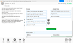
You are working to build an ESI-LAG for a multihomed server. The ESI-LAG is not coming up as multihomed.
Referring to the exhibit, what are two solutions to this problem? (Choose two.)
- The gateway IP addresses on both devices must be different.
- The LACP system ID on both devices must be the same.
- The loopback IP addresses on both devices must be the same.
- The ESI ID on both devices must be the same.
Correct answer: BD
Explanation:
According to the Juniper documentation1, an ESI-LAG is a link aggregation group (LAG) that spans two or more devices and is identified by an Ethernet segment identifier (ESI). An ESI-LAG provides redundancy and load balancing for a multihomed server in an EVPN-VXLAN network. To configure an ESI-LAG, you need to ensure that the following requirements are met:The LACP system ID on both devices must be the same. This ensures that the LACP protocol can negotiate the LAG parameters and form a single logical interface for the server.The ESI ID on both devices must be the same. This ensures that the EVPN control plane can advertise the ESI-LAG as a single Ethernet segment and synchronize the MAC and IP addresses of the server across the devices.The VLAN ID and VNI on both devices must be the same. This ensures that the server can communicate with other hosts in the same virtual network and that the VXLAN encapsulation and decapsulation can work properly.In the exhibit, the LACP system ID and the ESI ID on both devices are different, which prevents the ESI-LAG from coming up as multihomed. Therefore, the correct answer is B and D. The LACP system ID on both devices must be the same and the ESI ID on both devices must be the same.Reference:ESI-LAG Made Easier with EZ-LAG,Example: Configuring an ESI on a Logical Interface With EVPN-MPLS Multihoming,Introduction to EVPN LAG Multihoming According to the Juniper documentation1, an ESI-LAG is a link aggregation group (LAG) that spans two or more devices and is identified by an Ethernet segment identifier (ESI). An ESI-LAG provides redundancy and load balancing for a multihomed server in an EVPN-VXLAN network. To configure an ESI-LAG, you need to ensure that the following requirements are met:
The LACP system ID on both devices must be the same. This ensures that the LACP protocol can negotiate the LAG parameters and form a single logical interface for the server.
The ESI ID on both devices must be the same. This ensures that the EVPN control plane can advertise the ESI-LAG as a single Ethernet segment and synchronize the MAC and IP addresses of the server across the devices.
The VLAN ID and VNI on both devices must be the same. This ensures that the server can communicate with other hosts in the same virtual network and that the VXLAN encapsulation and decapsulation can work properly.
In the exhibit, the LACP system ID and the ESI ID on both devices are different, which prevents the ESI-LAG from coming up as multihomed. Therefore, the correct answer is B and D. The LACP system ID on both devices must be the same and the ESI ID on both devices must be the same.Reference:ESI-LAG Made Easier with EZ-LAG,Example: Configuring an ESI on a Logical Interface With EVPN-MPLS Multihoming,Introduction to EVPN LAG Multihoming
Question 9
In the case of IP Clos data center five-stage fabric design, what are two rotes of the super spines? (Choose two.)
- Super spines are used to interconnect two different data center pods.
- Super spines connect to all spine devices within the five-stage architecture.
- Super spines are used to connect leaf nodes within a data center pod.
- Super spines are always connected to an external data center gateway.
Correct answer: AB
Explanation:
In the case of IP Clos data center five-stage fabric design, the super spines are the devices that provide the highest level of aggregation in the network. They have two main roles:Super spines are used to interconnect two different data center pods. A pod is a cluster of leaf and spine devices that form a 3-stage Clos topology. A 5-stage Clos topology consists of multiple pods that are connected by the super spines. This allows for scaling the network to support more devices and bandwidth.Super spines connect to all spine devices within the five-stage architecture. The spine devices are the devices that provide the second level of aggregation in the network. They connect to the leaf devices, which are the devices that provide access to the end hosts. The super spines connect to all the spine devices in the network, regardless of which pod they belong to. This provides any-to-any connectivity between the pods and enables optimal routing and load balancing.The following two statements are incorrect in this scenario:Super spines are used to connect leaf nodes within a data center pod. This is not true, because the leaf nodes are connected to the spine nodes within the same pod. The super spines do not connect to the leaf nodes directly, but only through the spine nodes.Super spines are always connected to an external data center gateway. This is not true, because the super spines are not necessarily involved in the external connectivity of the data center. The external data center gateway is a device that provides the connection to the outside network, such as the Internet or another data center. The external data center gateway can be connected to the super spines, the spine nodes, or the leaf nodes, depending on the design and the requirements of the network.5-stage Clos Architecture --- Apstra 3.3.0 documentation5-Stage Clos Architecture | Juniper NetworksExtreme Fabric Automation Administration Guide In the case of IP Clos data center five-stage fabric design, the super spines are the devices that provide the highest level of aggregation in the network. They have two main roles:
Super spines are used to interconnect two different data center pods. A pod is a cluster of leaf and spine devices that form a 3-stage Clos topology. A 5-stage Clos topology consists of multiple pods that are connected by the super spines. This allows for scaling the network to support more devices and bandwidth.
Super spines connect to all spine devices within the five-stage architecture. The spine devices are the devices that provide the second level of aggregation in the network. They connect to the leaf devices, which are the devices that provide access to the end hosts. The super spines connect to all the spine devices in the network, regardless of which pod they belong to. This provides any-to-any connectivity between the pods and enables optimal routing and load balancing.
The following two statements are incorrect in this scenario:
Super spines are used to connect leaf nodes within a data center pod. This is not true, because the leaf nodes are connected to the spine nodes within the same pod. The super spines do not connect to the leaf nodes directly, but only through the spine nodes.
Super spines are always connected to an external data center gateway. This is not true, because the super spines are not necessarily involved in the external connectivity of the data center. The external data center gateway is a device that provides the connection to the outside network, such as the Internet or another data center. The external data center gateway can be connected to the super spines, the spine nodes, or the leaf nodes, depending on the design and the requirements of the network.
5-stage Clos Architecture --- Apstra 3.3.0 documentation
5-Stage Clos Architecture | Juniper Networks
Extreme Fabric Automation Administration Guide
Question 10
IBA probes analyze telemetry data from specified devices within a blueprint. Which component Identities devices that supply data tor a specific probe?
- data selector
- processor
- search engine
- graph query
Correct answer: D
Explanation:
A graph query is a component that identifies devices that supply data for a specific probe. A graph query is an expression that matches nodes in the Apstra graph database based on their attributes, such as device name, role, type, or tag.A graph query can be used to select the source devices for the input processors of a probe, as well as to filter the data by device attributes in the subsequent processors of a probe12.Reference:ProbesApstra IBA Getting Started Tutorial A graph query is a component that identifies devices that supply data for a specific probe. A graph query is an expression that matches nodes in the Apstra graph database based on their attributes, such as device name, role, type, or tag.A graph query can be used to select the source devices for the input processors of a probe, as well as to filter the data by device attributes in the subsequent processors of a probe12.
Reference:
Probes
Apstra IBA Getting Started Tutorial
HOW TO OPEN VCE FILES
Use VCE Exam Simulator to open VCE files
HOW TO OPEN VCEX AND EXAM FILES
Use ProfExam Simulator to open VCEX and EXAM files
ProfExam at a 20% markdown
You have the opportunity to purchase ProfExam at a 20% reduced price
Get Now!